Japan Earthquake | Page 1522
 @estacion Do you want me to translate if for you? You're missing the most important piece of information (you can't understand law if you only read bits and pieces).
"Lei n.o 12/2005 de 26 de Janeiro
Informação genética pessoal e informação de saúde
A Assembleia da República decreta, nos termos da
alínea c) do artigo 161.o da Constituição, a lei seguinte:
Artigo 1.o
Objecto
A presente lei define o conceito de informação de saúde e de informação genética, a circulação de informação e a intervenção sobre o genoma humano no sistema de saúde, bem como as regras para a colheita e conservação de produtos biológicos para efeitos de
testes genéticos ou de investigação."
"Object
The present law defines the concept of health information and genetic information, the circulation of information and the intervention on the human genome in the health system, as well as the rules of the collection and conservation of biological products for the purpose of genetic testing or research."
This is a law about DNA and other biological products regulation and information related to those. It is a very specific law. If you read further down (part of what you posted) it also says that information can be accessed for research purposes and others specified in the law (grey area... you need to read through the whole document to figure out what OTHER stands for). =)by Pedro Jesus 6/6/2011 7:51:23 PM Nuclear event in Egypt (06 June, 2011): hisz.rsoe.hu
"The Anshas nuclear reactor, located on the outskirts of Cairo, has leaked ten cubic meters of radioactive water for the second time in a year, according to Samer Mekheimar, the former director of the Nuclear Research Center’s atomic reactions department. Mekheimar submitted a note to the Supreme Council of the Armed Forces, saying the leakage took place on 25 May as a result of operating the reactor without taking into account safety precautions. He also said the Atomic Energy Agency kept the incident secret and threatened to fire the staff if they talked about it. “The fact that the reactor was by mere chance not operated the next day saved the area from environmental disaster,” he wrote. “All ministries were changed after the revolution, except the Ministry of Electricity and Energy,” he added. “It still kept the same minister and his deputies from the dissolved ruling party.” Meanwhile, sources at the Nuclear Safety Authority said they were denied entry to the reactor to conduct an inspection. Director of the Atomic Energy Agency, Mohamed al-Kolaly, said that levels of radiation inside the reactor are normal, and that the International Atomic Energy Agency has praised the reactor."by es 6/6/2011 7:54:10 PM- Radioactive Spill in United Kingdom (06 June, 2011): hisz.rsoe.hu
"An investigation has started into a spill of radioactive water from the submarine refit complex at Devonport dockyards. Operators Babcock said two holding tanks containing the water had overflowed over the weekend, but the spillage was kept in the dock basin. The Environment Agency said it was not aware of any environmental impact. A spokesman said it would be investigating and asking questions over procedures. Plymouth City Council said: "We will be waiting for the outcome of the investigation but are seeking urgent reassurances from the Ministry of Defence that this sort of incident will not happen again." Devonport is the main refitting base for Royal Navy nuclear submarines and has a number of decommissioned nuclear submarines awaiting dismantling. Water which has been used to cool the reactor on board nuclear submarines is irradiated with a substance called tritium. Once submarines are docked at Devonport, water containing tritium is treated and discharged to permitted levels into the River Tamar. Babcock said the incident happened after a hose pipe became detached from a tap.
Water from the tap went into the holding tanks, which had overflowed. Babcock said the water in the holding tanks was below the limit for discharged tritium. A spokesman said: "On discovery of the overflow early today, key staff were mobilised to manage the situation most effectively and the overflow has been contained and further discharges prevented. "The affected area is being returned to normal operation. The impact on normal business on the site has been minimal. "No personnel were contaminated or exposed to radiation." The Environment Agency said that radioactive discharges from Devonport were limited to 700 gigabecquerels a year, a becquerel being a unit of radioactivity. It believed the spill over the weekend was "less than one thousandth of 1% of that limit". A spokesman said: "No additional radioactivity was discharged into the environment. "At this stage we do not believe there is any environmental impact." The Office for Nuclear Radiation said it would be investigating but the quantity of radioactive material released "poses no risk to people on or off site"."by es 6/6/2011 7:54:28 PM  Fukushima: Twice As Bad As Thought
One recurring theme that has emerged after Fukushima is the tendency of nuclear experts to underestimate (publicly at least) the severity of the disaster. Today we received further proof of this when the Japanese government more than doubled the estimate for the amount of radiation released from the plant in the immediate aftermath of the crisis in March.
ecocentric.blogs.time.comby Panserbjorne9 6/6/2011 7:54:42 PM Twice would be nice, I'm thinking. Given TEPCO's tendency to release late, release low, and update with "deep regret" repeatedly, we'd almost have to conclude that, if they're admitting to double, it's probably quadruple at least.by radioguy 6/6/2011 8:01:36 PM
 I asked about it this weekend, the high building reading. I wonder if the #1 RPV pressure sensors were really bad or if some kind of blowout occurred, the sudden pressure "drop" being related to the venting of highly radioactive steam within the building.by Markfm 6/6/2011 8:04:17 PM
- That's certainly the simplest explanation. We'll see if it turns out to be correct. (Or maybe we won't, given information flow on this.)by radioguy 6/6/2011 8:09:56 PM
- This plant is operating so far out of nominal, though, it's hard to even know which broken, twisted, exploded part to blame.by radioguy 6/6/2011 8:10:54 PM
- @Pedro Jesus: What part of "The present law defines the concept of health information and genetic information" don't you understand?
If your legislators have decided to make a law that includes two matters and you don't like it, I suggest you an appeal against it.
You're missing the most important piece of information (you can't understand law if you only read bits and pieces).
Precisely.
FYI, this law is the only law that regulate this matter (Health and History Data Records of patients) in Portugal.
By the way, this law (in the data record aspect) doesn't differ to much about European directive.)by estacion 6/6/2011 8:13:05 PM - EQ 05:10 JST 07 Jun 2011 37.8N 141.6E 40 km M4.5 Fukushima-ken Okiby estacion 6/6/2011 8:23:42 PM
- Is this about the same guys from the Telegraph story? If so they apparently escaped with their lives.
www.japantoday.com
I find it remarkable that this never made the news at the time.
It also makes me wonder what amount of radiation these guys have been exposed to? Same question goes for all those that were there at the time of the explosions and fires.
In this version of the story the debris was blown 70 meters up in the air. Imo it was a lot higher than that.
search.japantimes.co.jpby nls 6/6/2011 8:27:48 PM  the way tepco, IAEA and govJ are handling the disaster and decieving the public is an example that none of us should ever forget. the same would happen in every other country. we should abstract from the japanese events and question our own countries' policies. they all will treat us like children and deceive us if we let them.by Edano 6/6/2011 8:30:23 PM
- @nls 70 meters would barely have cleared the stacks. They didn't see the Reactor 3 explosion video?by radioguy 6/6/2011 8:33:07 PM
- @Edano I completely agree with you.by estacion 6/6/2011 8:33:41 PM
- @nls : it seems to be the same crew as in the telegraph. it's a funny coincidence that these reports come out now, nearly 3 months after, while we are dicussing the case. strange. a very good find.by Edano edited by Edano 6/6/2011 8:35:42 PM

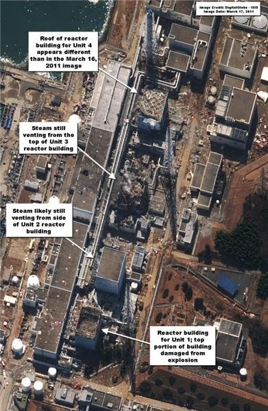
isis-online.org
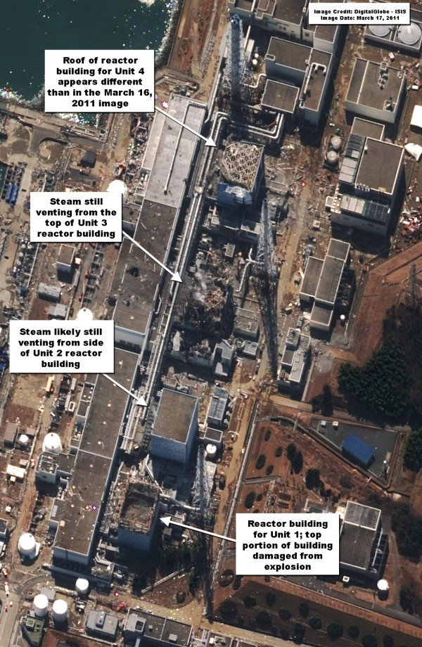
@nls an easier way to see it is to look at the roofs of the buildimgs nearby, they are clear of debris so that blast was enough to sent hefty chunks of concrete far . I find it hard to imagine without picturesby elainekirk via Isis-online.org 6/6/2011 8:36:16 PM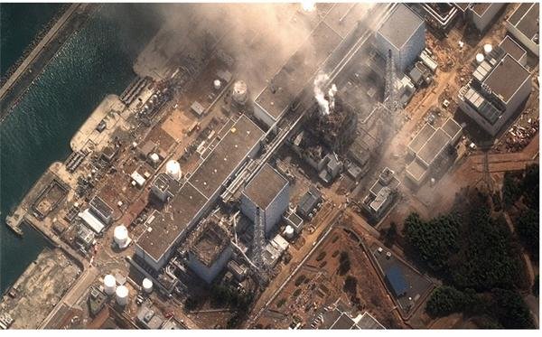
@nls this image from Digital Globe showseven better how clear those roofs are www.flickr.com
by elainekirk 6/6/2011 8:39:57 PM- by radioguy 6/6/2011 8:41:27 PM
- @estacion I don't want to argue about this. I can see you read Portuguese so, please check Artigo 4º of that law to confirm what I was saying about the availability of health information. Artigo 4º - 3, 4 and 5. For research purposes you don't even need authorization, you only need to safeguard anonymity. There are different levels of access defined by the amount of information that can be released to certain entities. There is no secrecy. Any entity working within the health system (including private, independent entities such as labs or clinics) has a certain level of access to health information for different purposes (including statistic which falls in the scope of research).
You were right about the scope of this law, though. Like I said (and you pointed out), "you can't understand law if you only read bits and pieces". That applies to me as well. I took some time to read the document more thoroughly. It does regulate all health information. The emphasis on genetic products is probably due to the previous lack of legislation regarding that particular subject.by Pedro Jesus 6/6/2011 8:47:50 PM 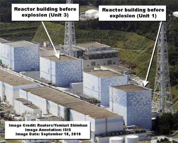
@nls and just for novelty value here are the four units with roofs
by elainekirk 6/6/2011 8:50:31 PM- @elainekirk I had forgotten how they looked like not so long
ago.by Pedro Jesus 6/6/2011 8:51:50 PM - @elainekirk @Pedro Jesus @nls We get so used to looking at them, we forget how much of them is gone. I think we also forget the impact when people see them. I pull up a page of photos for people who FOLLOW the news, and they are blown away.by radioguy 6/6/2011 8:56:10 PM
- Because you don't see this if you follow "The News".by radioguy 6/6/2011 8:56:40 PM
- @elainekirk roofs :) yes one would almost forget what it is supposed to look like
that digital globe image was taken three minutes after the explosion. probably these military firefighters are in the picture then.by nls 6/6/2011 8:58:58 PM 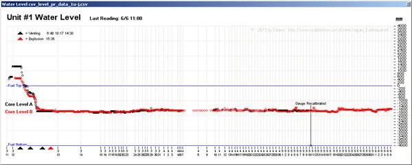
www.houseoffoust.com
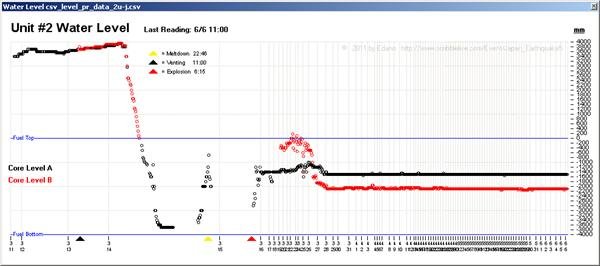
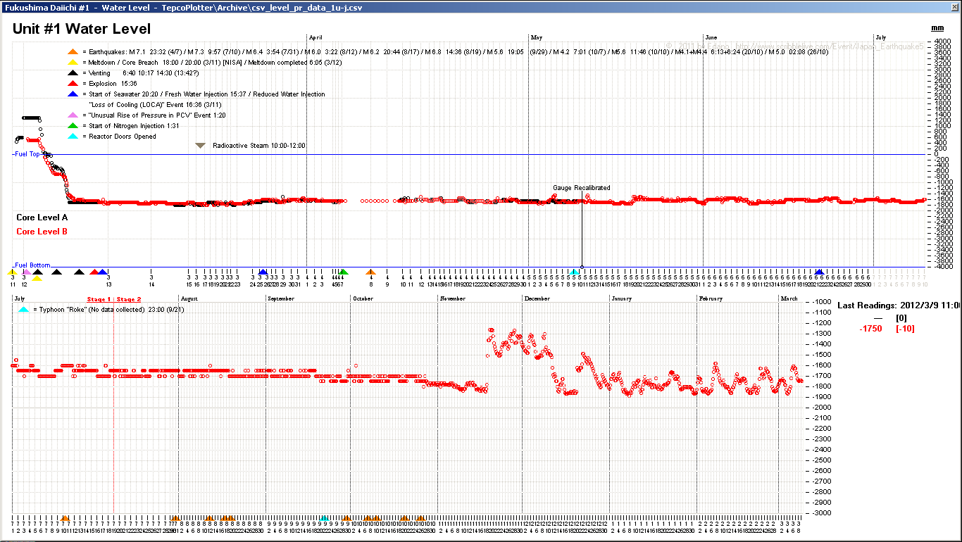
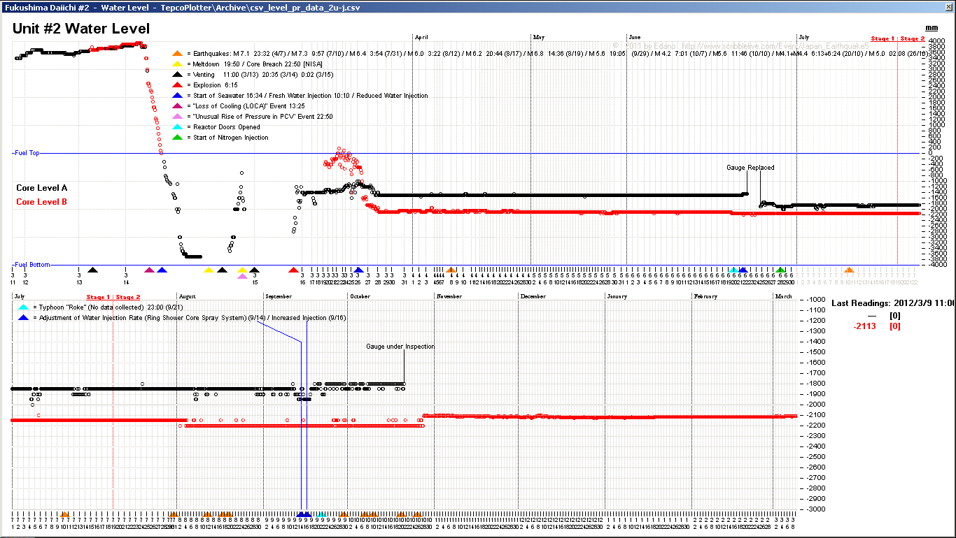
according to NISA the meltdown in #1 occured at about 19:46 on march 11, after 3 hours without water. if this is true, tepco's sensor data must be manipulated (the first reading is 19:30, March 11). www3.nhk.or.jpby Edano via Houseoffoust edited by Edano 6/6/2011 9:00:48 PM- "Japan's nuclear regulator says the meltdown at one of the Fukushima reactors came about 5 hours after the March 11th earthquake, 10 hours earlier than initially estimated by the plant's operator.
The government's Nuclear and Industrial Safety Agency on Monday issued the results of its analysis of data given to it by Tokyo Electric Power Company."
i do not feel comfortable exploring that.by Edano 6/6/2011 9:07:27 PM - seawater was not injected before March 12:
"March 12th 20:20 Started to inject seawater and borated water to the Reactor Core." www.nisa.meti.go.jpby Edano 6/6/2011 9:10:23 PM - so why the hell shows the sensor > 4 meters ???by Edano 6/6/2011 9:11:14 PM
- @edano it is one helluva mess!!by elainekirk 6/6/2011 9:14:36 PM
- given the reactor was not damaged by the earthquake [tepco], the sensors should be working, or not ?by Edano 6/6/2011 9:15:47 PM
- @Edano I think we all agree (and TEPCO has so confirmed lately) that some of sensors readings were not to be trusted. If it is due to manipulation or malfunction, that is still to be understood. They've been replacing, recalibrating and or repairing most gauges at #1, #2 and #3, have they not? But, I'm curious. Why do you say data might have been manipulated? Core meltdown does not require that all the water has evaporated prior to the occurrence of partial meltdown. And, according to a simulation dean has shared maybe a week or so ago, once partial meltdown starts the process develops very quickly (within hours). The molten core does not instantaneously breach through the RPV bottom, particularly if there's still some water inside. That data could still be right. Molten fuel starts to breach and leak through the bottom of the RPV and TEPCO starts injecting seawater to keep the (low) level and try and delay the total meltdown. I'd love to see some expert analysis on this. It could answer a few more questions about the whole mess.by Pedro Jesus 6/6/2011 9:17:52 PM
- @Edano On the other hand, it would require an accurate reading of the water level for TEPCO to be able to keep it so even over time, considering that it is constantly leaking to the basement. Hmm...by Pedro Jesus 6/6/2011 9:19:59 PM
- @Pedro Jesus : please read my posts carefully and look at the graph.by Edano 6/6/2011 9:22:17 PM
- @Edano I did. Could you please elaborate? What makes you think data has been tampered with? I can see where the water level suddenly decreases (it actually corroborates the assumptions in that simulation dean shared not long ago) and I can see no change after calibration suggesting that particular sensor was in fact working well. What else do you see?by Pedro Jesus 6/6/2011 9:32:45 PM
www.houseoffoust.com
#2 data fits better.by Edano via Houseoffoust 6/6/2011 9:33:07 PM- @Edano Or is it something we don't see that lead you to that assumption?by Pedro Jesus 6/6/2011 9:35:52 PM
- How mny mox assemblies were loaded into #3?by elainekirk 6/6/2011 9:42:41 PM
 @elainekirk 32! Do I win a prize? :-)by lillymunster 6/6/2011 9:45:52 PM
- Oooh Fuku trivia..by lillymunster 6/6/2011 9:46:06 PM
- @elainekirk It was less than 6% so 32 sounds correct.by Pedro Jesus 6/6/2011 9:50:10 PM
- @lillymunster The prize is yours.by Pedro Jesus 6/6/2011 9:50:23 PM

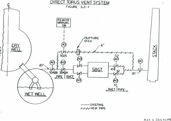
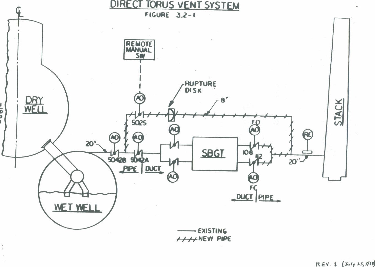
for @ fitter and the record: I found an engineer's explanation for this schemata on hardened vents www.beyondnuclear.org . Here is the link: josephmiller.typepad.com . Below an excerpt: "This design change (Figure 1b) provides a direct vent path from the torus to the main stack bypassing the Standby Gas Treatment System (SBGTS). The bypass is an 8" line whose upstream end is connected to the pipe between primary containment isolation valves AO-5042 A & B. The downstream end of the bypass is connected to the 20" main stack line downstream of SBGTS valves AON-108 and AON-112. An 8" butterfly valve (A0-5025), which can be remotely operated from the main control room, is added downstream of 8" valve AO-5042B. This valve acts as the primary containment outboard isolation valve for the direct torus vent line and will conform to NRC requirements for sealed closed isolation valves as defined in NUREG 0800 SRP 6.2.4. The new pipe is ASME III Class 2 up to and inclusive of valve AO-5025. Test connections are provided upstream and downstream of AO-5025.
The design change replaces the existing AC solenoid valve for AO-5042B with a DC solenoid valve (powered from essential 125 volt DC), to ensure operability without dependence on AC power. The new isolation valve, AO-5025, is also provided with a DC solenoid powered from the redundant 125 volt DC source. Both of these valves are normally closed and fail closed on loss of electrical and pneumatic power. One inch nitrogen lines are added to provide nitrogen to valves AO-5042B and AO-5025. New valve AO-5025 will be controlled by a remote manual key-locked control switch. During normal operation power to the AO-5025 DC solenoid will also be disabled by removal of fuses in the wiring to the solenoid valve. This satisfies NUREG 0800 SRP 6.2.4, Containment Isolation System acceptance criteria for a sealed closed barrier. An additional fuse will be installed and remain in place to power valve status indication for AO-5025 in the main control room.
A 20" pipe will replace the existing 20" diameter duct between SBGTS valves AON-108, AON-112 and the existing 20" pipe to the main stack. The existing 20" diameter duct downstream of AO-5042A is shortened to allow fitup of the new vent line branch connection.
A rupture disk will be included in the 8" piping downstream of valve AO-5025. The rupture disk will provide a second leakage barrier. The rupture disk is designed to open below containment design pressure, but will be intact up to pressures equal to or greater than those which cause an automatic containment isolation during any accident conditions.
New 8" vent pipe (8"-HBS-44), including valve AO-5025 is safety related. Vent piping downstream of AO-5025, including SBGTS discharge piping to main stack, is also safety related. All safety related piping will be supported as Class I. Nitrogen piping is non-safety related and will be supported as Class II/I." so fitter can read it at work, :)by Peter Melzer via Beyondnuclear.org 6/6/2011 9:51:44 PM- @elainekirk , the pics of the reactors you posted solve one question I posed yesterday. On the photo taken after unit 3 explosion, the pipe to the tower is broken. Unit 4 is still intact. Hence, Tepco's hypothesis that this is from where the hydrogen flowed to unit 4 is false. :)by Peter Melzer 6/6/2011 9:57:34 PM
- @hi peter I didnt know you were here I thought of you I have 1 more if you want it?by elainekirk 6/6/2011 9:59:51 PM
- @Peter Melzer : i think they meant the hydrogen was transferred before the explosion. of coursse the density was lower in #4.by Edano 6/6/2011 10:00:15 PM
Japan Earthquake | Page 1522
- Who's Blogging
-
 hudebnik
 alblee
 UKVal
UKVal Jonathan Keebler
 Oliver (ScribbleLive)
 kaykodh
 Markfm
 Angie
Angie Mid Valley
 Matt (ScribbleLive)
 George Gibb
- elainekirk
 PKelley
- lillymunster
 dean
dean bo
bo Edano
Edano Deb
Deb- Pedro Jesus
 IanGoddard