Japan Earthquake | Page 2553
 @dean would the water level drop be tied to the times they had to temporarily shut down cooling ala evaporation or could it indicate a leak?by lillymunster 10/25/2011 1:33:17 PM
 (Reuters) - Tokyo Electric Power has restored the cooling system of the nuclear reactor and fuel pool at the No. 5 unit of the crippled Fukushima Daiichi power plant in northeastern Japan, an official of the plant operator said on Sunday.
Tokyo Electric, know as TEPCO, said the cooling facility restarted at 12:49 p.m. (0349 GMT) and was expected to lower temperatures which had risen at the reactor and fuel pool after the cooling system stopped working late on Saturday.
The temperature at the nuclear reactor at the No.5 unit was up to 87 degrees Celsius (188 degrees Fahrenheit) at 8:00 a.m. (2300 GMT) from about 68 degrees before the cooling system stopped operating, the official said.by dean 10/25/2011 1:36:29 PM- @dean is that from this week?by lillymunster 10/25/2011 1:37:19 PM
- www.reuters.com @ lilly.. it must have been earlierby dean 10/25/2011 1:38:07 PM
- I thought that early on the No 5 plant lost cooling and resulted in the pressure increasing so valves were opened to bleed off pressure and resulted in water level lowering in the reactor vesselby dean 10/25/2011 1:39:20 PM
- @dean early on, like March-May?by lillymunster 10/25/2011 1:41:07 PM
- www.upi.com @ lilly.. I think it's happened more than once..by dean 10/25/2011 1:42:55 PM
- Dean, looking through old events at 5, finding repeated stoppages of pumps at 5.by lillymunster 10/25/2011 1:43:01 PM
- At approx. 5:24pm on March 23, the temporary Residual Heat Removal System Seawater Pump automatically stopped when its power source was switched. We restarted the pump at 4:14pm, March 24, and resumed cooling of reactors at4:35pm.
At 9:14 pm on May 28, we found that one temporary residual heat removal
system seawater pump of Unit 5 stopped. At 8:12 am on May 29, replacement work to the spare pump started. After finishing the replacement work, we started the pump at 12:31 pm, and restarted cooling from 12:49 pm. - At 9:00 am on June 8, we suspended the Residual Heat Removal System Pump (C) in order to increase one more pump. Two pumps resumed at 0:35 pm on the
same day.by lillymunster 10/25/2011 1:43:34 PM - At 6:55 am on July 3, our employee found a leakage of seawater from the water pipe (exit side) of one of the outside temporary seawater cooling pumps (2 pumps) of the residual heat removal system for the reactor. We stopped the pump at 10:00 am on the same day and confirmed stop of the leakage. We stopped the residual heat removal system of the reactor at 10:15 on the same day. We stopped another seawater pump at 10:20 on the same day and replaced the defected water pipe.After that, we resumed the operation of the seawater cooling pumps at 1:22 pm and 1:36 pm on the same day, and we resumed the operation of the residual heat removal system at 1:40 pm on the same day.by lillymunster 10/25/2011 1:44:19 PM
- As a countermeasure against seawater leakage from the piping of the outside temporary residual heat removal seawater system of the residual heat removal system of the Unit 5 occurred on July 3, we bound the piping tightly. However we found the similar part after reconfirmation of the site, in terms of preventive maintenance, we stopped the residual heat removal system at 6:30 am on July 13, stopped outside temporary seawater cooling pump at 6:44 am, and then replaced the piping. We restarted the residual heat removal system at 10:58 am. (outside temporary seawater cooling pump restarted at 10:52 am.by lillymunster 10/25/2011 1:44:58 PM
- At 10:16 am on July 15, we activated pumps of regular residual heat removal
seawater system (system B) of Unit 5 and began a trial run. At 2:45 pm on the same date, we started operation of Residual Heat Removal Systemby lillymunster 10/25/2011 1:46:36 PM - Unit 6 notes from before august all talk about water transfers of what is building up in the basement of 6.by lillymunster 10/25/2011 1:48:14 PM
- @ lilly .. good history information.. the tsunami/EQ combo must have wiped out the RHR system cooling capabilities... remember from the system diagram.. the RHR takes a low pressure low temp source of water from the PCV piping and runs it through the RHR heat exchanger which is cooled by the seawater system.. and also the RHR can be valve lined to provide cooling to the SFP. they must have set up a temporary seawater system that kept failing and failing up to when they returned the normal line up system on 7-15by dean 10/25/2011 1:49:20 PM
- @ lilly.. after seeing the inside of unit #1 and the damage caused it's no surprise that # 5 & 6 would have similar damageby dean 10/25/2011 1:50:09 PM
- Unit 5 more current events
From 10:03 am to 10:43 am on August 8, we stopped the residual heat removal system pump (D) in order to switch the power source of the pump (C) as well as conducting its commissioning (C) - In order to repair the outlet valve of Unit 5 residual heat removal system seawater
pump (D), from 9:45 am to 10:42 am, September 26, we switched the seawater pump from B system (permanently installed) to A system (temporarily installed). - On September 30, as the repair work for the outlet valve of Unit 5 Residual Heat Removal System Sea Water Pump completed, between 11:30 am and 11:34 am on the same day, the Residual Heat Removal System was switched from A system to B
(the Residual Heat Removal System Sea Water Line was also switched from A system to B).
- For the purpose of Unit 5 water intake inspection, at 9:05 am October 20, unit 5 seawater pump of Equipment Water Cooing System was shutdown, and stopped cooling the spent fuel pool. At 9:13 am, Residual Heat Removal System (D) was stopped and stopped cooling the reactor. As the inspection was completed, at 2:32 pm, seawater pumps of Equipment Water Cooing System was resumed, which resumed
cooling the spent fuel pool. At 3:02 pm, Residual Heat Removal System (D) was resumed, which resumed cooling the reactor. Due to this stop, reactor water temperature temporarily rose from 22.2℃ to 31.1℃. Spent fuel pool water temperature temporarily rose from 25.5℃ to 26.2℃.by lillymunster 10/25/2011 1:50:16 PM - Could the heat exchanger have a small leak?
I remember reading they can get pin holes and rust leaks. Hamaoka found one in one of their units post quake.by lillymunster 10/25/2011 1:51:29 PM - @ lilly.. it is possible to get a leak in the heat exchanger and, if that happened you would have primary coolant water leaking into the sea water cooling side of the seawater system,,, then we'd have to know where the discharge piping goes (probably to some combined pipe that takes water to the main discharge header back to the ocean)by dean 10/25/2011 1:54:14 PM
- what amazes me is there are other systems in the plant through which water should be available to cool the reactor and the spent fuel pool.. are they saying that none of these systems are functional? hmmmmmmby dean 10/25/2011 1:55:27 PM
- RHR systems takes over after all the decay heat has been removed and those facilities have been down for more than ample time to do that... with normal plant heat removal systems..by dean 10/25/2011 1:56:15 PM
- @dean sounds like it. Not talking about them or using them sort of implies not operating in TEPCO-ese.by lillymunster 10/25/2011 1:56:25 PM
- @ lilly.. indeed, or saying.. "the plant in cold shutdown use only RHR system to save power bill"by dean 10/25/2011 1:57:53 PM
- @dean they talk about alternative seawater systems. Then about using the permanent system. So maybe there is an issue with the intakes? I am not familiar enough with what they should look like to tell on both of them. The one that looks like a vertical pipe with a base with holes in it looked normal, reminds me of industrial water systems equipment. The other one I have no basis to have a clue what I was looking at.by lillymunster 10/25/2011 1:58:39 PM
- @ lilly.. can you imagine the BROKERS for these utility companies sitting at the big table trying to negotiate how much the power is going to cost between then during outage periods.. I imagine the raise the prices to make a profitby dean 10/25/2011 1:59:11 PM
- @dean Elaine posted some rockhopper gathered info from the workers. They are in major cost cutting efforts at the plant. Reusing tyvek, getting rid of any workers at the plant not essential to safety work and asking workers to take on additional tasks.by lillymunster 10/25/2011 1:59:46 PM
- @dean there is already discussion of a huge rate increase in Japan.by lillymunster 10/25/2011 2:00:14 PM
- @ lilly.. would you like a quicky overview of those types of pumps?by dean 10/25/2011 2:01:16 PM
- by dean 10/25/2011 2:05:06 PM
- The bottom of this one looks damaged. Checking for the video that had the part that didn't look familiar www.tepco.co.jpby lillymunster 10/25/2011 2:05:29 PM
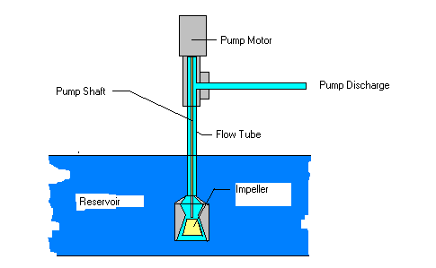
verticle lift simple diagram
by dean 10/25/2011 2:05:48 PM- many things can cause the impellers to be damaged and loose efficiency, or the bell housing the impellers to be damaged.. I suspect that the motors, which are 2-3000 HP were ruined, piping system damaged along with the impellers so a temp system would be set up and hoses run to link the system up...by dean 10/25/2011 2:08:59 PM
- the worst thing on those types of pumps that can cause accelerated damage is cavitation and that probably was a serious problem at fukuby dean 10/25/2011 2:09:52 PM
- Found what was confusing me. Auxillary Sea Water Pump unit 5. About half way through the video they are filming what looks like lifted up concrete and a piece of tubing. www.tepco.co.jpby lillymunster 10/25/2011 2:12:37 PM
- checking nowby dean 10/25/2011 2:13:12 PM
- buffering is taking for ever on that one..by dean 10/25/2011 2:14:02 PM
- can't open it @ lilly.. I did see it one time as you explainby dean 10/25/2011 2:15:13 PM
- let me grab a quick screen shotby lillymunster 10/25/2011 2:19:08 PM
- I have it going nowby dean 10/25/2011 2:19:18 PM
unit 5 asw intake
by lillymunster 10/25/2011 2:20:32 PM- the bottom bell which has the first impeller has piping extending down adn that pipe is damaged and fallen apart,,,,by dean 10/25/2011 2:20:49 PM
- examining the debris at the bottom of the .. "wet well" is what it's called.. could damage the impellars by being sucked up inby dean 10/25/2011 2:21:57 PM
- I can see all kinds of abnormalities in that videoby dean 10/25/2011 2:22:45 PM
- @dean the other system had a pipe end fallen off. In the background of that screenshopt. it looks like an angled gap in a concrete wall? Is that what that is or am I reading into it?by lillymunster 10/25/2011 2:23:58 PM
- the pump shafts are usually housed in a concrete well.. ie: concrete box... the intake system has screens etc and wire filters to remove debris that may come in and fill the wet well with as clean of water as possible..by dean 10/25/2011 2:24:04 PM
- your reading it right.. all that is broken piping and the wall, which is usually nice smooth concrete is pitted..by dean 10/25/2011 2:24:47 PM
Japan Earthquake | Page 2553
- Who's Blogging
-
 hudebnik
 alblee
 UKVal
UKVal Oliver (ScribbleLive)
 Jonathan Keebler
 kaykodh
 PKelley
 Markfm
 Angie
Angie Deb
Deb Mid Valley
 Pedro Jesus
 Matt (ScribbleLive)
 George Gibb
 elainekirk
- lillymunster
- dean
 bo
bo Edano
Edano IanGoddard