Japan Earthquake | Page 2248
 I just emailed the Washington Post reporter who wrote an article about N. Anna this week and told him about what we've foundby Panserbjorne9 8/26/2011 3:22:20 PM
 @Panserbjorne9 outstanding!by lillymunster 8/26/2011 3:23:37 PM
 Archive on these values:
Lake Anna Conditions
Lake Anna's water level and temperature readings are updated once each weekday. The temperature is measured in water being drawn directly from the main lake into the station's intake. The lake level is based on feet above sea level as measured at the main dam.
Date Temperature (deg. F) Lake Level (ft.)
8/26/2011 84 249.7by estacion 8/26/2011 3:23:38 PM- @estacion are there specific dates, months or years you want?by lillymunster 8/26/2011 3:24:25 PM
- No, we need data dates prior to EQ to compare to actual values.by estacion 8/26/2011 3:25:47 PM
- @estacion archive.org hasn't been tracking the page. Google's cached copy is this morning.
@all Obama is coming on national media to do some sort of address about Ireneby lillymunster 8/26/2011 3:28:01 PM  Would there not be other (public?) authorities measuring the lake level too, not just the NPP?by es 8/26/2011 3:28:26 PM
- @es I would think so. I looked at the Dom page source code hoping to find their data source with no luck.by lillymunster 8/26/2011 3:30:39 PM
- @es Corps of engineers and weather agencies track Missouri river levels, we used those to track the flooding at Ft. Cooper..by lillymunster 8/26/2011 3:31:13 PM
 Found this description here www.nrc.gov ( 2.4.6.1 Summary of Technical Information in the Application ): "North Anna Intake Structure
The North Anna intake structure, located on the shore of the North Anna reservoir is an
eight-bay (four bays serve each unit) reinforced-concrete structure supported by a reinforced concrete mat foundation on soil. The intake structure draws water from the reservoir and
provides cooling water to the main condensers for both units. There are two reinforced concrete wing walls on the waterside corners of the intake structure to direct water into the bay.
The interior walls of the intake structure separate the eight bays. Each bay has an associated
circulating water pump and two of the bays have a motor-driven auxiliary service water pump.
The auxiliary service water pump house and fire pump house are located on the exposed deck
of the intake structure. The safety-related auxiliary service water pump house, fire pump
house, and the intake structure control house at the west side of the intake structure are within
the scope of license renewal. The electrical cable that runs from the intake structure control
house to the auxiliary fire pump is routed in a concrete duck bank (in the area of yard
structures) which is supported by the intake tunnel header. Therefore, the intake tunnel header
is also within the scope of license renewal.
The outlet water from the main condensers is directed to a reinforced-concrete discharge tunnel
(one for each unit). The Unit 2 discharge tunnel combines with the Unit 1 discharge tunnel
(opposite to Unit 1 condensers) to form a common tunnel which shares an inner wall. The two
tunnels terminate at a seal pit, which is a reinforced-concrete outlet structure. The discharge
tunnels and the seal pit are within the scope of license renewal."by Peter Melzer 8/26/2011 3:33:07 PM For North Anna, the CW (circulating water ) system does not transport the ultimate heat sink flow and therefore
was mostly not concluded to be in scope. The inspectors agreed with this conclusion.
The North Anna Power Station lake Intake Structure contains the CW intake tunnel header,
Auxiliary SW Pump House, Fire Pump House, and Intake Structure Control House. The Intake
Structure is located on the shore of the North Anna reservoir (Lake Anna). Circulating water is
withdrawn from the Lake Anna into the Intake Structure to provide cooling water for the main
condensers for Units 1 and 2. Backup, auxiliary SW for Units 1 and 2 and make-up water for
the separate, SW spray pond, the ultimate heat sink, is also provided from the Intake Structure,
through separate water lines. The Intake Structure is an eight-bay (four bays per unit)
reinforced concrete structure that serves both units. There is a total of eight trash racks, but
only the two trash racks associated with the safety related auxiliary SW Pump House and one
trash rack associated with the auxiliary fire pump are within the scope of license renewal.
With its different configuration, the North Anna site has in scope two auxiliary SW pumps that
are installed in the main circulating water intake structure on Lake Anna and four main SW
pumps at the SW reservoir pump house. SW is normally recirculated through the plant via the
main pumps and back to the spray pond. The auxiliary pumps are able to provide an alternate
supply of water to the SW supply headers. An alternate return path is also provided to the
Circulating Water discharge tunnel from the SW return headers. The auxiliary pumps or the notin-scope screen wash pumps can make up to maintain the level of the SW reservoir www.nrc.govby elainekirk 8/26/2011 3:38:12 PM- water info from geology.com for Virginia geology.comby lillymunster 8/26/2011 3:41:41 PM
- This has streamflow for the N Anna river but I can't identify where the lake is. waterwatch.usgs.govby lillymunster 8/26/2011 3:45:52 PM
- USGS announced the day before the quake about large gas deposits in the area. www.usgs.govby lillymunster 8/26/2011 3:48:25 PM
- North Anna
pbadupws.nrc.gov plant drawingsby elainekirk 8/26/2011 3:48:47 PM - @Peter Melzer: That's a good description of installation. Moreover it appears like correct according to Google satelite map view.by estacion 8/26/2011 3:52:00 PM
- My US geography is not great but I looked at the kmz file and then the data for this station (from lillys link): 01670400 NORTH ANNA RIVER NEAR PARTLOW, VA - waterdata.usgs.govby es 8/26/2011 3:53:37 PM
- Google KMLs: waterwatch.usgs.govby es 8/26/2011 3:54:59 PM
- Nuclear and Industrial Safety Agency Ministry of Economy on August 26 accident and TEPCO Fukushima Daiichi Nuclear Power Station, published a document summarizing the amount of each type of radioactive material were released into the atmosphere by atomic bombs dropped on Hiroshima was. And simple calculation, the emission of a nuclear accident is 168.5 times the cesium 137 atom bomb, equivalent to 2.5 times the iodine-131. translate.google.comby elainekirk 8/26/2011 3:57:49 PM
 28,000 acre WILDfire (rangeland..think lots of sagebrush) at Idaho National Laboratories near Idaho Falls. inlportal.inl.govby Cryptococcus 8/26/2011 4:01:15 PM
- Idaho fire prompts evacuation of nuclear facility (Reuters) - Firefighters struggled on Thursday to control a fast-growing 28,000-acre wildfire raging within several miles of spent nuclear fuel stored at a U.S. Energy Department lab in the high desert of eastern Idaho.
The growth and intensity of the blaze, the nation's largest active wildfire, prompted the Idaho National Laboratory to order a key facility on the 890-square-mile site evacuated of all nonessential personnel, lab officials said.
The Materials and Fuels Complex, about 38 miles from Idaho Falls, consists of facilities for handling, processing and examining spent nuclear fuel, irradiated materials and radioactive wastes, according to the lab's website. www.reuters.comby Cryptococcus 8/26/2011 4:02:51 PM - So... according to that data, at USGS 01670400 NORTH ANNA RIVER NEAR PARTLOW, VA (Station operated in cooperation with Virginia Dominion Power) there was a measured increase in Daily Mean Discharge of 12 cubic feet per second between the 23rd and the 24th August - the discharge was 41 cubic feet per second on the 23rd, 50 on the 24th and 51 on the 25th.by es 8/26/2011 4:05:56 PM
- Oops bad math - increase of 10 cubic metres per second totalby es 8/26/2011 4:07:15 PM
- 9 cubic feet per second between the 23rd and the 24th Augustby es 8/26/2011 4:07:41 PM
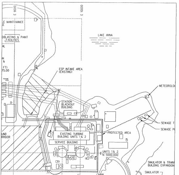
North Anna intake structure pbadupws.nrc.gov
by elainekirk 8/26/2011 4:24:02 PM- Lake Anna water-level bill shelved in state legislature [February 11, 2009]: fredericksburg.comby es 8/26/2011 4:31:45 PM
 @es Thanks for that page of river gauge KML's. Very useful.
@Hank Scorpio, who pages back said he couldn't trust RT to be anything besides anti-American propaganda: I can't trust the current US MSM to be anything but anti-American propaganda.
This far into the past few years of monumental change in the news-gathering and distribution arena, we should really be beyond thinking like that. Face it, we've all seen enough propaganda to call bullsh*t on it when we see it, whatever its origin or original language. When the US media drops a critical story like a hot potato, or like they've been paid off, you find news from those who haven't been, or have been paid off by other people. Then you read through the spin and zero in on the truth.
Anyone who avoided media over a name and its associated negative spin, missed the best reporting on the WikiLeaks story on Al Jazeera, and has basically missed one of the only mainstream news organizations that never dropped the story, RT.
@lillymunster GREAT work getting that together and to RT.by RadioGuy 8/26/2011 4:37:14 PM @all Good Morning...Good Afternoon...Hello!by smoss 8/26/2011 4:38:31 PM
- @smoss g'day :)by RadioGuy 8/26/2011 4:38:50 PM
- @smoss Hi!by lillymunster 8/26/2011 4:39:17 PM
- @all NUCLEAR PLANTS AT THE READY
Progress Energy said it was taking safety precautions at its two-unit Brunswick nuclear plant in Southport, North Carolina, where the storm was expected to pass nearby on Saturday. The plant, 22 feet above sea level, is built to withstand winds of 128 miles per hour.
National Hurricane Center Director Bill Read warned on Thursday that Irene could blast up the East Coast with Category 2 storm force, packing winds of 96 to 110 mph.
"Being a large hurricane, tropical storm-force winds will extend far inland," he warned.
Nuclear plant operator Public Service Enterprise Group said it was securing equipment against storm winds at its Salem and Hope Creek plants, along the Delaware River in Hancocks Bridge, New Jersey.
Checks "are being conducted for objects that could become airborne", said Skip Sindoni, a spokesman for PSEG.
The plants could be taken offline if the storm causes the Delaware River to rise rapidly, he added.
At Indian Point, the large nuclear plant just 38 miles north of New York City, operator Entergy was "securing all material and equipment outside buildings and ensuring that we have a sufficient supply of diesel fuel for backup generators," said spokesman Jim Steets
www.reuters.comby smoss 8/26/2011 4:39:50 PM - @es, as much as I could tell from google maps, this flow measuring station must be located downstreams of Lake Anna. I find an increase of 7 cubic feet/s between Aug. 23 and 24 in the table. This corresponds to 0.2 cubic meters/s or 17,280 cubic meters/day. That increase cannot account for the loss we estimated earlier.
Gotta go buy water, just in case, and be back soon, :)by Peter Melzer 8/26/2011 4:40:33 PM - @Radioguy@lillymunster I am having less and less time to pop in, but when the earthquake hit, this was the first place I checked for breaking news! @all Thank you for the contiuned coverage and great work!by smoss 8/26/2011 4:42:10 PM
- I believe your math over mine Peter. Take care out there :)by es 8/26/2011 4:42:36 PM
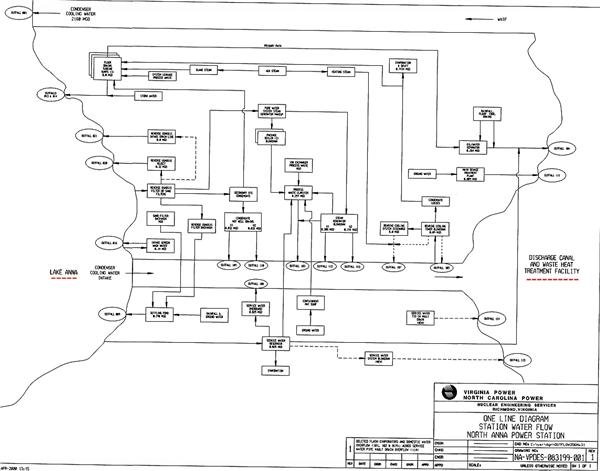
North Anna station water flow diagram pbadupws.nrc.gov
The NAPS currently operates two 890 megawatt nuclear power units. The existing units
(Unit I & 2) employ a once-through cooling system, drawing lake water from the 9,600 acre
Lake Anna. The cooling system then discharges to three lagoons connected by a series of canals.
Discharges to the three lagoons ultimately flow to Lake Anna. docs.google.com
.
site blueprints - pbadupws.nrc.gov
.
Lots of geology mapping etc for Anna pbadupws.nrc.govby elainekirk 8/26/2011 4:43:24 PM- @all Nuclear power plants prepare for expected hurricane www.power-eng.comby smoss 8/26/2011 4:47:03 PM
- hi smoss! I agree. Great resource and interesting crowd sourcing info.by Cryptococcus 8/26/2011 4:48:20 PM
 Wow, you guys have done some amazing research on Lake Anna! Heres a new photo of Unit 3 : cryptome.orgby Ian 8/26/2011 4:48:23 PM
- @all The size and power of the storm would at this point imply of course that some nuclear plant sites might experience Loss Of Offsite Power ("LOOP", which our long time readers know all about) but quickly we realize after reading the above article that not only are the sites of all owner-operators aware of the approach of this storm, they're taking action and some will shut down long in advance of the approach of any damaging weather forces.
atomicpowerreview.blogspot.comby smoss 8/26/2011 4:48:34 PM - The NRC found that the performance of Unit 1 at the North Anna plant met all of the
agency’s safety objectives in 2010 and was at a level that results in no additional NRC oversight.
However, Unit 2 faces some additional oversight and inspections in 2011 due to a white
performance indicator for four unplanned reactor scrams, or shutdowns, during the last four
quarters that exceeded a threshold for unplanned scrams per 7,000 hours of operation. docs.google.comby elainekirk 8/26/2011 4:48:57 PM - Here is a good historical report of Lake Anna filled with plenty of data. I can't find anything strange with actual measured readings of Dominions web page.
www.lakeannavirginia.orgby estacion 8/26/2011 5:14:58 PM - @Ian That is quite the picture. Off to see what I can pull out of it.by lillymunster 8/26/2011 5:18:08 PM
- @lillymunster, it's taken from the same angle as some others. Apart from its high res, I'm not sure there's 'new data', but better resolution is always helps.by Ian 8/26/2011 5:24:49 PM
- @Ian mainly just better resolution so you can see things.by lillymunster 8/26/2011 5:27:13 PM
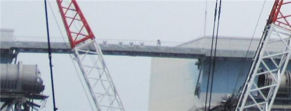
pipe
by lillymunster 8/26/2011 5:31:57 PM
Japan Earthquake | Page 2248
- Who's Blogging
-
 hudebnik
 alblee
 UKVal
UKVal Oliver (ScribbleLive)
 Jonathan Keebler
 kaykodh
 PKelley
 Markfm
 Angie
Angie Deb
Deb Mid Valley
- Pedro Jesus
 Matt (ScribbleLive)
 George Gibb
- elainekirk
- lillymunster
 dean
dean bo
bo Edano
Edano IanGoddard