Japan Earthquake | Page 2572
 @Peter just trawling , if they are there I will find :)by elainekirk 10/29/2011 5:34:33 PM
- what floor would you gues at peter ?by elainekirk 10/29/2011 5:45:34 PM
- @Peter peter I have the outside picsby elainekirk 10/29/2011 5:50:48 PM

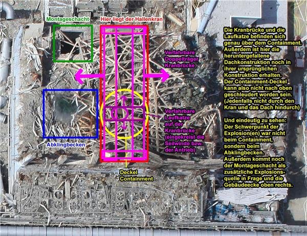
i just found that. not related to anything.
by Edano via Fukushima.physikblog.eu 10/29/2011 5:50:59 PM- @Edano do we have these pics docs.google.comby elainekirk 10/29/2011 5:55:01 PM
- @elainekirk ooh i don't know you must ask lilly.by Edano 10/29/2011 5:55:51 PM
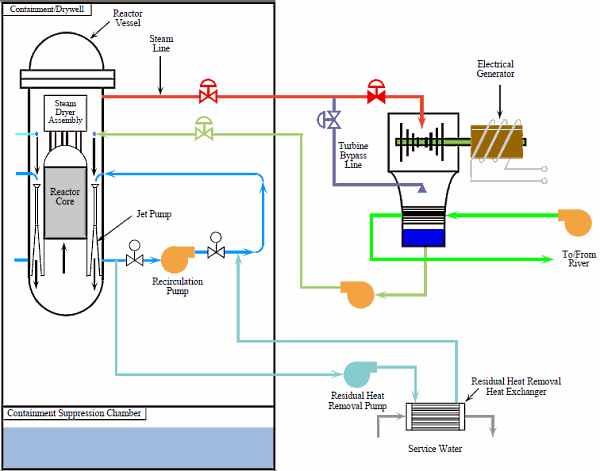
just random pics
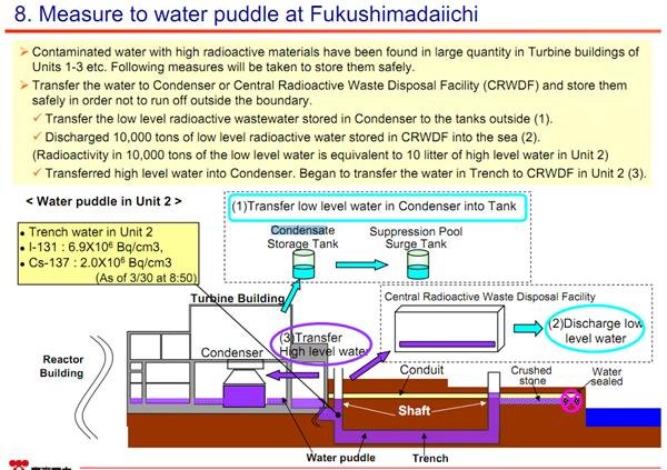
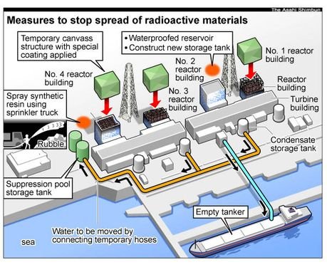
by Edano via World-nuclear.org 10/29/2011 5:56:41 PM- @Edano these condensate storage tanks peter asked about have been used to store contaminated water from turbine buildings www.tepco.co.jp
Draining water from underground floor of turbine buildings
-At 1:55 pm April 3rd, in Unit 1, water transfer from the condenser to
the condensate storage tank was commenced.
-From 5:10 pm, April 2nd to 1:10 pm, April 9th, in Unit 2, water in the
condenser was transferred to the condensate storage tank.
-On April 7th, we knocked holes in the external walls (including louvers)
of turbine buildings at Units 2 to 4 in order to get the draining hoses
through to the Central Environmental Facility.by elainekirk 10/29/2011 5:58:08 PM 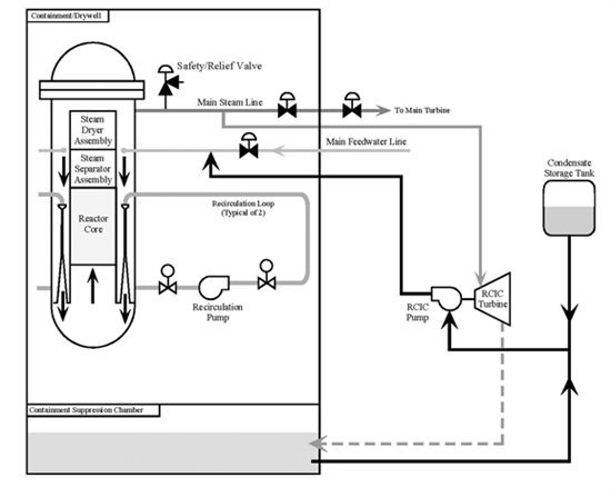
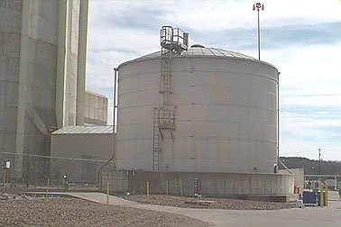
nuclearstreet.com here is the condensate storage tank.
by Edano via Nuclearstreet 10/29/2011 5:58:10 PM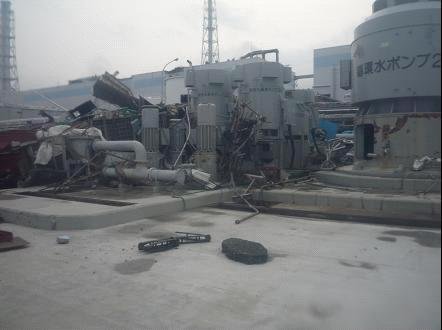
www.tepco.co.jp
@Edano so they are the tanks in the photos of that doc I just posted ? docs.google.comby elainekirk via Tepco.co.jp 10/29/2011 6:00:21 PM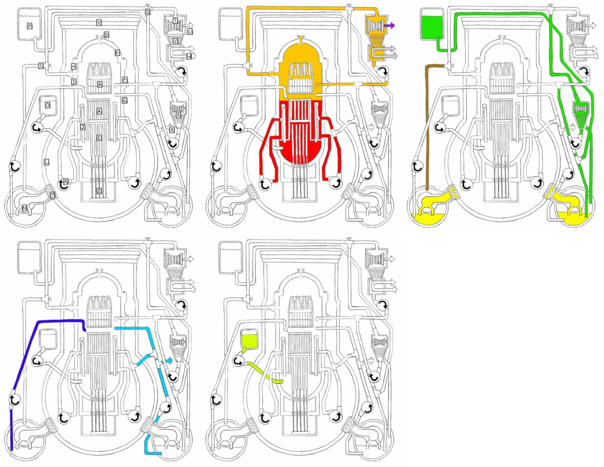
i.picasion.com
hey, now this is cool:
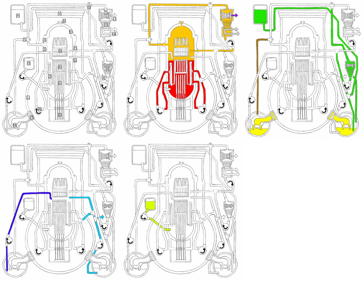
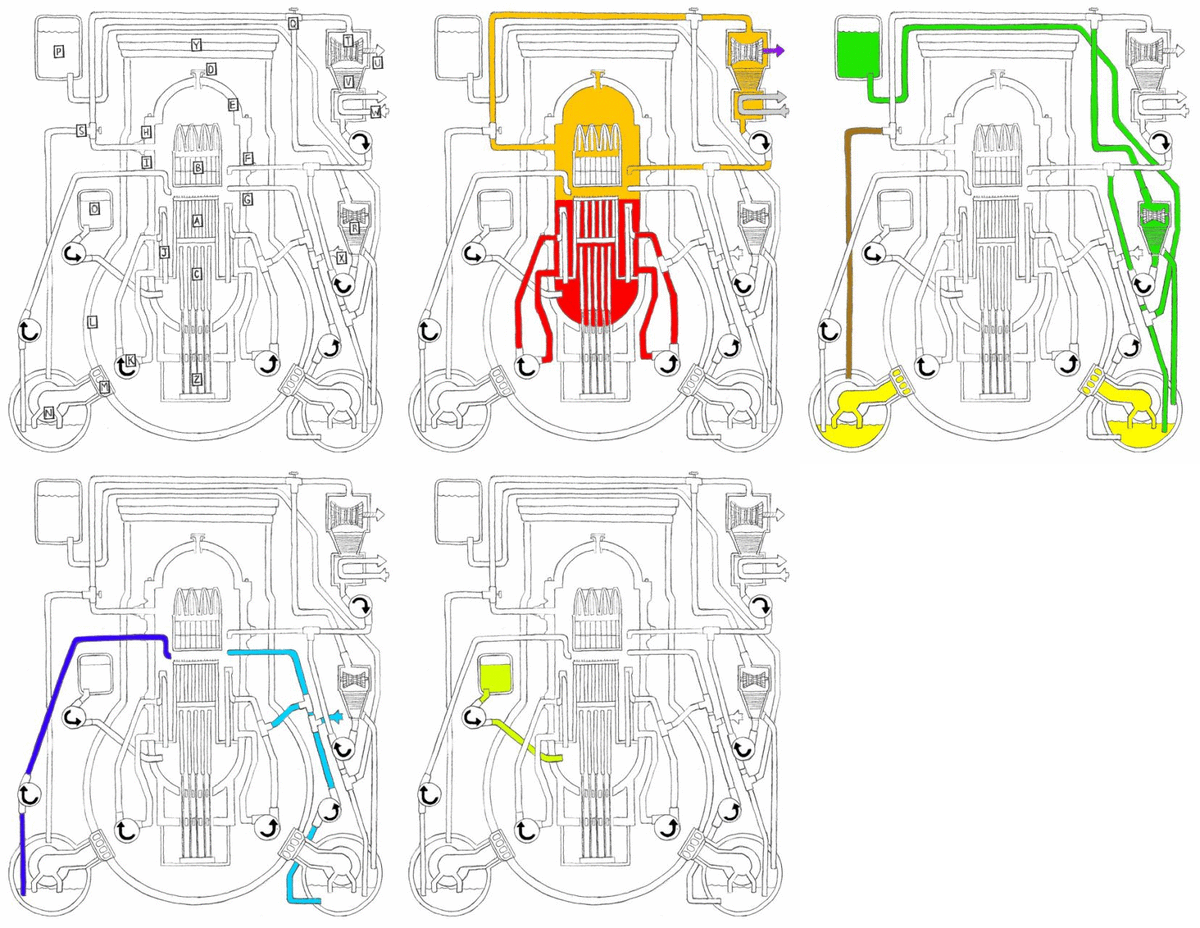
Mark I Reactor Components: (A) Uranium fuel rods; (B) Steam separator and dryer assemblies (C) Graphite control rods; (D) Vent and head spray; (E) Reactor vessel; (F) Feedwater inlet; (G) Low pressure coolant injection inlet; (H) Steam outlet; (I) Core spray inlet; (J) Jet pump; (K) Recirculation pump; (L) Concrete shell "drywell"; (M) Venting system; (N) Suppression pool; (O) Boron tank; (P) Condensate storage tank; (Q) High pressure coolant injection system; (R) HCIS turbine; (S) Automatic depressurization system; (T) Main turbine; (U) Connection to generator; (V) Condenser; (W) Circulating water; (X) Connection to outside service water; (Y) Concrete shield plug; (Z) Control rod drives. Illustrations by Joe Kloc. motherjones.comby Edano via I.picasion 10/29/2011 6:02:34 PM- @elainekirk i have no idea :)by Edano 10/29/2011 6:04:28 PM
 I thought those tanks were outdoors, but I may be mistaken.by Peter 10/29/2011 6:04:54 PM
- @Peter they must be outdoors
"Draining water from underground floor of turbine buildings
-At 1:55 pm April 3rd, in Unit 1, water transfer from the condenser to
the condensate storage tank was commenced.
-From 5:10 pm, April 2nd to 1:10 pm, April 9th, in Unit 2, water in the
condenser was transferred to the condensate storage tank."by elainekirk 10/29/2011 6:05:24 PM - the last pic is animated !by Edano 10/29/2011 6:05:28 PM
- @Edano @Edano it wont animate for me :)by elainekirk 10/29/2011 6:06:33 PM
- @elainekirk no, click on the link.by Edano 10/29/2011 6:06:57 PM
 by M.I.A. via Algor 10/29/2011 6:07:12 PM
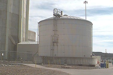
- That's tha Arkansas One condensate storage tankby M.I.A. 10/29/2011 6:07:43 PM
@elainekirk *pics\0126284993079a8910455db963b9ad93.gif*
by Edano via I.picasion 10/29/2011 6:08:10 PM- @Edano COOLby M.I.A. 10/29/2011 6:08:53 PM
motherjones.com
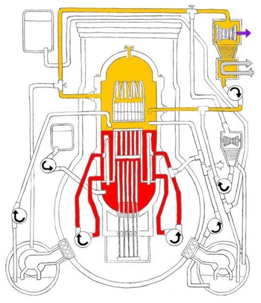
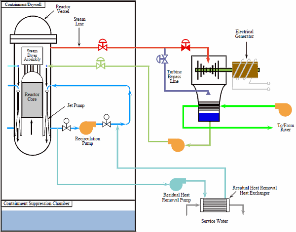
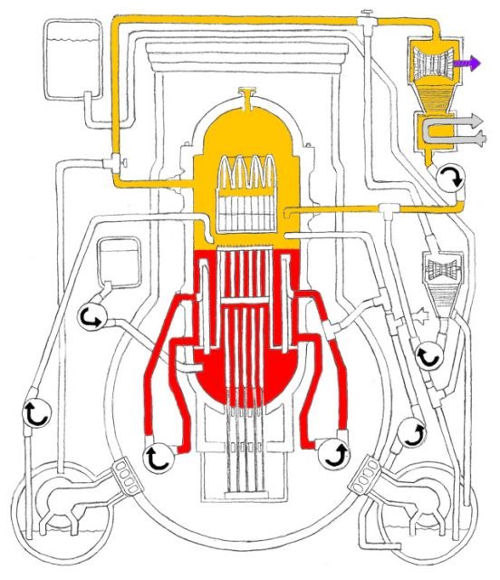
Mark I Reactor Running Normally: Recirculation loops (RED) keep pressurized water circulating through the uranium core of the reactor. When water is heated by the uranium core it turns to steam. It passes through the steam separator and dryer assemblies positioned above the core (ORANGE) and then moves through the steam pipe. The steam is used to turn a turbine connected (PURPLE) to an electrical generator. It is then turned back into liquid by a condenser and cooled by a pipe (GREY) of circulating cold water. The water is then pumped back into the reactor, where the process begins again.by Edano via Motherjones 10/29/2011 6:09:44 PM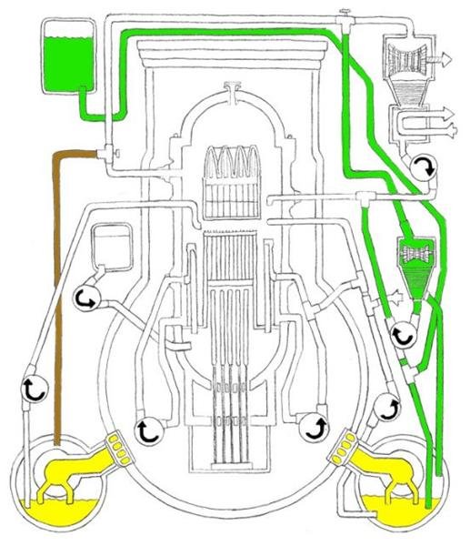
motherjones.com
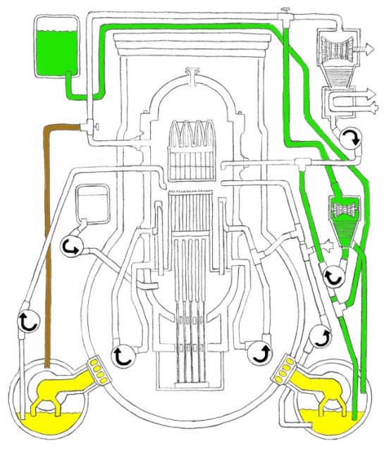
Mark I Reactor High Pressure Emergency Core Cooling System: The Automatic Depressurization System (BROWN) can be used to release pressure in the reactor. It reroutes some of the steam to the suppression chamber. The High Pressure Coolant Injection System (GREEN) takes steam from the steam pipe and converts it into water that is then pumped back into the reactor to keep the core cool. Pressure can also be released directly (YELLOW) into the suppression chamber.by Edano via Motherjones 10/29/2011 6:10:21 PM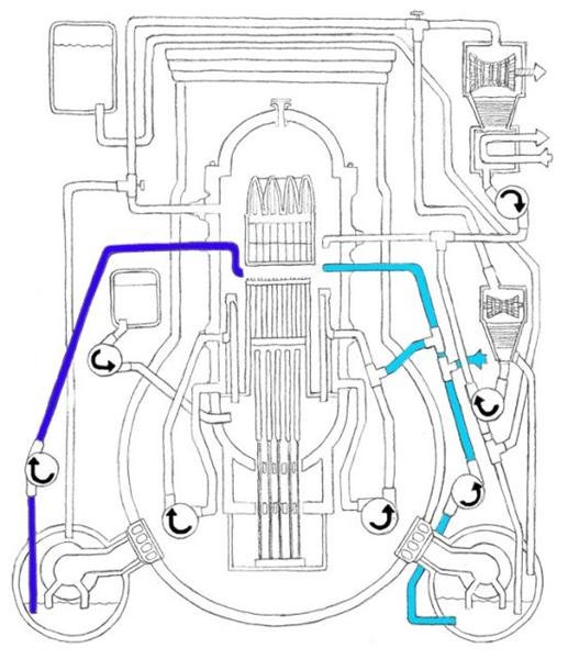
motherjones.com
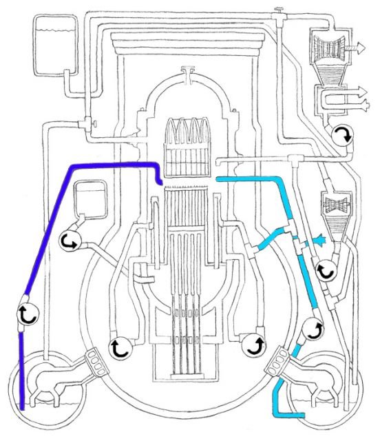
Mark I Reactor Low Pressure Emergency Core Cooling System: The Core Spray System (DARK BLUE) takes water from the suppression chamber and sprays it onto the core. The Low Pressure Coolant Injection System (LIGHT BLUE) takes outside water as well as water from the supression chamber and pumps some into the recirculation system (shown as RED in first diagram) and sprays the rest on the core.by Edano via Motherjones 10/29/2011 6:10:53 PM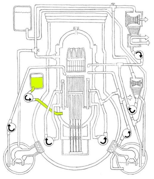
motherjones.com
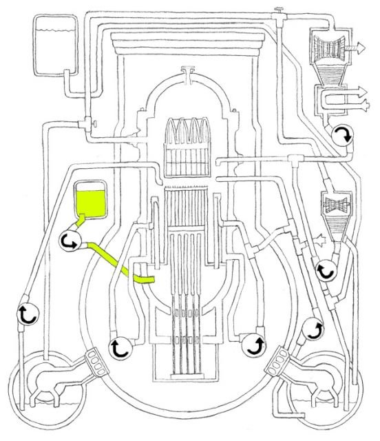
Mark I Reactor Standby Liquid Control System: Most of the Fukushima reactors are powered by low enriched uranium. When the LEU is hit with neutrons, the atoms split, releasing energy (which heats the water) and more neutrons. Because boron (LIME) absorbs neutrons, injecting it into the core can help shut down the reactor.by Edano via Motherjones 10/29/2011 6:11:33 PM- edano, the animation works for me on chrome. It is kind of cool!by Peter 10/29/2011 6:11:49 PM
- @M.I.A. , thanks, I was expecting something in this size. Each unit should have one. If tepco was able to transfer water into them, they must have survived earthquake, tsunami and explosions. Still the piping to the turbine-driven pumps could have been disrupted.by Peter edited by Edano 10/29/2011 6:12:17 PM
- @Peter now we all understand what only you understand ! ;)by Edano 10/29/2011 6:12:47 PM
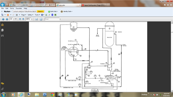
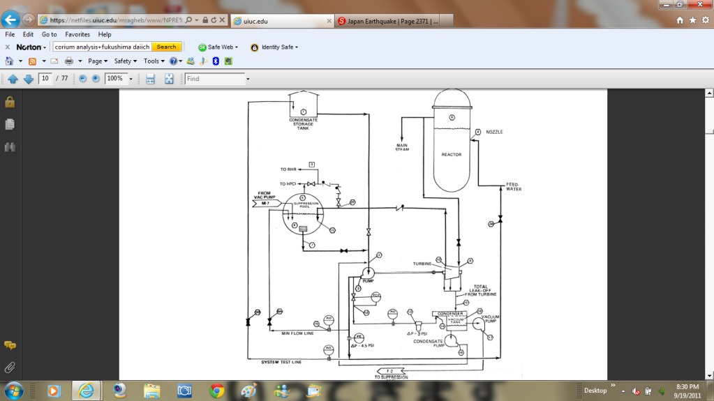
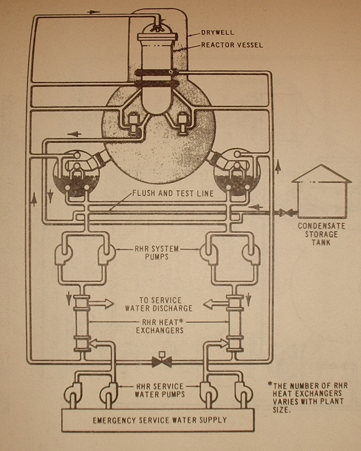
- @Edano , what I am after is on the top left in the anim. It connects to the turbine-driven pump, middle right. The piping is a bit convoluted, but this pump sucks water, depending on the setting of a three way valve, first from the storage tank and, when that does not work, from the torus suppression pool, and pumps it into the rpv to keep the water level above the fuel. Interestingly, the piping from the tank to the pump is not as quake-proof as the pipe from the pump to the rpv. The tank built on soil and the pump in the reactor building built on rock rattle to different tunes during a quake which might rupture the tank connection or damage the valve such that no water is pumped. The valve must be actuated from the control room.by Peter 10/29/2011 6:22:07 PM
 by M.I.A. via I1207.photobucket 10/29/2011 6:25:46 PM
- I should add that this system is only used during emergency shutdowns, when the main steam loop through the power-generating turbine and its condenser is not available.by Peter 10/29/2011 6:26:00 PM
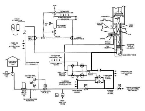
- @M.I.A. , yes, on this scheme the tank is in this little house. Why do they use a house as the symbol for a tank?by Peter 10/29/2011 6:27:25 PM
- @Peter Storage 'shed' symbol? Idk. The only thing I'd add to your excellent tutorial is that the turbine that pulls water from the tank is decay-steam driven, so a lack of power won't normally shut it down.by M.I.A. 10/29/2011 6:31:55 PM
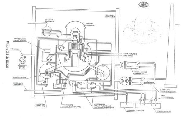 by Edano via Bravenewclimate.files.wordpress 10/29/2011 6:32:32 PM
- it is strange, there is no pic of the tank, though i search hard.by Edano 10/29/2011 6:33:12 PM
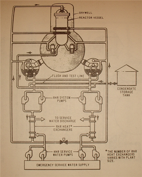
1.bp.blogspot.com again, a house.
by Edano via 1.bp.blogspot 10/29/2011 6:35:06 PM- ooo pics :) good find edanoby elainekirk 10/29/2011 6:35:55 PM
- i found it !!!!!!!!!!!!!by Edano 10/29/2011 6:37:33 PM
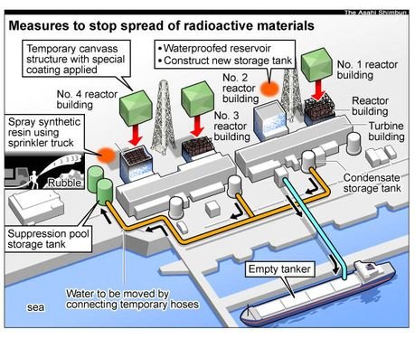
there we go !
by Edano via Dwqovw6qi0vie.cloudfront.net 10/29/2011 6:37:49 PM- @M.I.A. , that is correct. There are three pumps like this in this type of reactor, one for the Reactor Core Isolation Cooling system and the other two (a booster and a main pump) for the High Pressure Coolant Injection system. Should the steam pipes break, the pumps won't work.by Peter 10/29/2011 6:39:19 PM
 hi all - back briefly while I grab lunch. Will go back and grab all these cool illustrations your finding later today when I have time to sit down.
Per Edano's records of quakes vs. these changes at 3. I wonder if something just finally failed leading to 3's changes? Will look back at all the posts later.by lillymunster 10/29/2011 6:39:53 PM- @lillymunster if you scroll there is a control buildings diagramby elainekirk 10/29/2011 6:41:25 PM
- by elainekirk 10/29/2011 6:42:39 PM
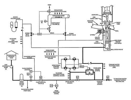
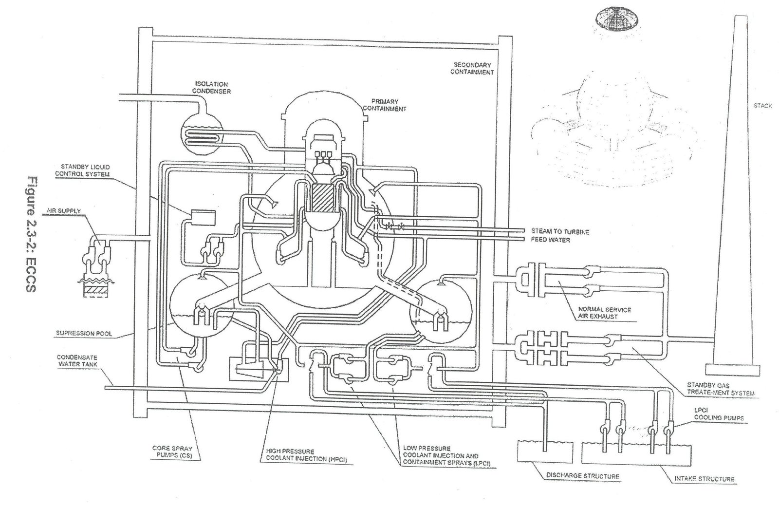
One more diagram (house and all) 'cuz it shows some other stuff, too. media.tumblr.com
by M.I.A. via Media.tumblr 10/29/2011 6:43:13 PM- @elainekirk score! Will remember to go grab itby lillymunster 10/29/2011 6:45:38 PM

Japan Earthquake | Page 2572
- Who's Blogging
-
 hudebnik
 alblee
 UKVal
UKVal Oliver (ScribbleLive)
 Jonathan Keebler
 kaykodh
 PKelley
 Markfm
 Angie
Angie Deb
Deb Mid Valley
- Pedro Jesus
 Matt (ScribbleLive)
 George Gibb
- elainekirk
- lillymunster
 dean
dean bo
bo- Edano
 IanGoddard