Japan Earthquake | Page 979
 TEPCO's latest planned 'Improvement of the environment within the Reactor Building of Unit 1' [4 May, 2011]: www.tepco.co.jp
(as per attachment in TEPCO Press Release [May 04, 2011] - Report Instruction regarding Improvement of the working environment inside the reactor building of Unit 1, Fukushima Daiichi Nuclear Power Station: www.tepco.co.jp )by es 5/4/2011 9:00:34 PM The Tokyo Electric Power Co., Inc. (TEPCO) announced that operating
revenues for the FY 2010 third quarter - the third quarter
net income was 139.8 billion yen (116.0 billion yen on a non-consolidated
basis)
www.tepco.co.jp
If ave month = 30days x by 3 (months) =90 days =
1.54 billion a DAYby elainekirk 5/4/2011 9:04:09 PM
jim:
apan Atomic Power said it may shut No. 2 reactor at its Tsuruga nuclear plant due to a technical problem.
The company said it identified a possible leak of iodine from the 1,160MW reactor's nuclear fuel assemblies into its coolant.
According to the company, 4.2 becquerels of iodine-133 and 3,900 becquerels of xenon gas were detected per cubic centimeter, up from 2.1 becquerels of iodine and 5.2 becquerels of xenon deteced earlier.
Japan Atomic said there may be a pin hole created in a zirconium alloy encasing fuel pellets and added that there had been no radiation leak from the facility.
Tsuruga nuclear plant is located 280 miles west of Tokyo in Fukui prefecture.
The plant is located in an area that is not affected by the adverse earthquake and subsequent tsunami that hit Japan on 11 March 2011.
nuclear.energy-business-review.comby Jim Carver 5/4/2011 9:23:09 PM oops two hours without a word ?by Edano 5/4/2011 9:27:59 PM
- @edano methinks something iffy is afoot we have much activity at this time normallyby elainekirk 5/4/2011 9:32:56 PM
- @jim they don't seem too worried they have their plans
www.tepco.co.jpby elainekirk 5/4/2011 9:35:08 PM  About time--this website from radioguy helps alot www.timeanddate.com . Also see my links page oldbooks.net/fukushimaby billmcd 5/4/2011 9:36:00 PM
 @estacion You asked about sunrise in Japan. Here is the next few days for sunrise/ sunset. May 5, 2011, 4:46 AM --6:30 PM
May 6, 2011, 4:45 AM --6:31 PM
May 7, 2011, 4:44 AM --6:32 PMby ms in la 5/4/2011 9:42:38 PM- by Jim Carver 5/4/2011 9:43:16 PM
- tepco said elsewhere 9 days to install the equipment to clean the air before they can start planning to send in workers
...by elainekirk 5/4/2011 10:02:22 PM  Alot of steam from #2 and #4by marie rich 5/4/2011 10:03:23 PM
 @marie rich just got back in and checked the cam. It really is churning out lots of steam. When I looked at 4 it was going in waves and a solid contained plume out of the SFP. It must be boiling really good right now. BTW, I received an email from one of the reporters. They are being told verbally from TEPCO that the SFP at 3 and 4 are averaging 80-90 degrees celsius. They didn't know why TEPCO or any of the agencies were not putting this in paper reports but they are getting regular verbal numbers for that at least.by Nancy 5/4/2011 10:14:00 PM
 Yet there is the jt article talking to 8 going in thursday.by Markfm 5/4/2011 10:14:03 PM
- Convenient to not give out the readings from the new instruments they were supposed to have put in #4 sfp back on 22 april or thereabouts.by Markfm 5/4/2011 10:15:56 PM
- Elaine, the bottom sticky is mucked up, any chance you could groom it? (hard to do on phone)by Markfm 5/4/2011 10:22:20 PM
- @mark ok strange thing to happen?!by elainekirk 5/4/2011 10:27:20 PM

Heh, they got the cameraman the tripod...
by Rob in SF 5/4/2011 10:30:03 PM- @thunder sorry you had somehow got into mod but you are now on autoby elainekirk 5/4/2011 10:30:03 PM
- @Thunder, I didn't get an email yet. The rapidshare file went to rapidshare's home page.
by Nancy 5/4/2011 10:35:14 PM - @Nancy Got an email from Mahjjam via egnyte with videos. I'm having alot of trouble with my ISP (rat-bastards), my internet speed has dropped to as low as 6kbs. Can't always answer, sorry.
by marie rich 5/4/2011 10:45:41 PM 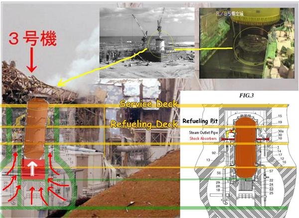
s7.directupload.net
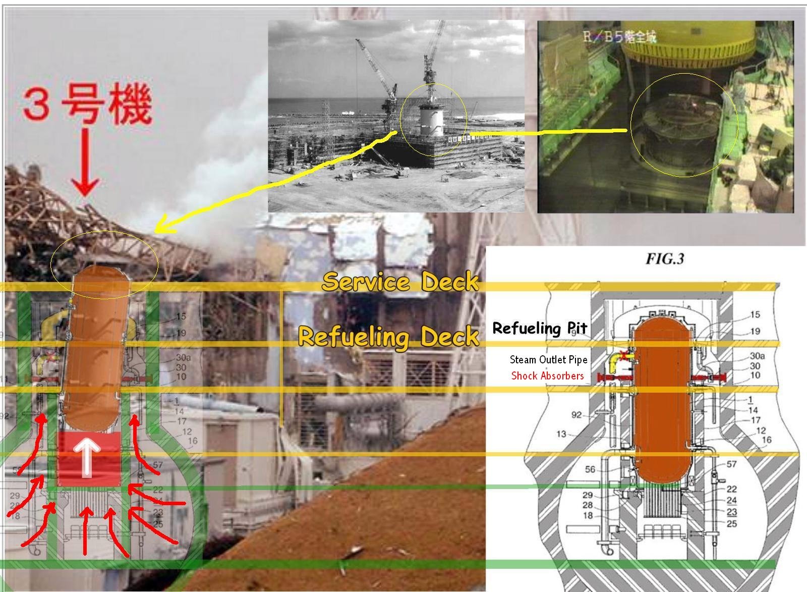
I made some overlay revealing the mystery of #3 explosion
at first i will quote a longer explanation from www.physicsforums.com . FHM is the (yellow) containment cap:
< The short answer is that a hydrogen explosion on the top floor does not explain what we see and cannot launch the FHM upward. That is the key.
The only thing that launches the FHM upward is steam, because if all the water is gone, then the pool is just full of hydrogen like the rest of the upper floor and there is no differential pressure under the FHM when it blows.
How do we get steam under the FHM? Only way is superheated gas blasting out the transfer chute.
How does that happen? The containment is full of nitrogen and hydrogen venting occurs to the outside of the containment.
Remember the lateral acceleration forces from the 9.0 quake that exceeded the design parameters of Unit 3? I was wrong about the weak spot being the torus-to-primary containment link.
Here is a radiologist's interpretation of Fig. 3, which is the critical information needed here.
That big old steel reactor vessel sets on a pedestal like a long, skinny boiled egg. It is made of heavy steel, and it is full of water and one of the densest things I know of -- uranium.
The structures in red are pneumatic shock absorbers of some sort. They are intended to stabilize said "egg" in an earthquake if anything gets tippy.
The torus is in the ground and all that massive concrete structure, not to mention the steel liner inside the primary containment are MASSIVE and firmly anchored to the ground.
If the lateral acceleration forces exceed the design parameters, the pressure vessel risks becoming the upside down clanger in a giant bell shaking at about a 9 on the Richter scale.
The key vulnerable structure if that happens is the high pressure steam outlet pipe. If that cracks or leaks, then you have high pressure steam and shortly thereafter, hydrogen in the primary containment, but not in a huge blast, as the torus suppression pool is meant to (hopefully) handle. Apparently that didn't work out so well at Unit 2.
Now, I can put live steam and hydrogen gas in the primary containment displacing the nitrogen. I can't tell you the exact route to the lower building -- probably via the torus pool then lower floors and up through the lift shaft.
Anyway, pressure differential vs. atmospheric pressure in the vessel doesn't go to zero, but neither does the pressure build to the same level as an RPV without the damaged pipe and leak. Operators might interpret that as "hold off a short while and let's hope to God the generator gets hooked up and we can cool this off before the pressure goes too high, because Unit 1 exploded when we had to do that the last time!" *
Addendum:
*actually the operators had already manually vented the primary containment at 8:42 AM -- but perhaps this also let to more hydrogen in the upper containment, but it means the leak, if there was one either was not so large as to negate the need to vent the RPV, or, perhaps that the rising pressure in the RPV added to the severity of the leak before it was vented.
In the meantime, some hydrogen could have escaped the the drywell cap seal as well as the transfer gate seal, maybe even a pressurized stream venting to the upper building.
The reactor vessel is now mostly dry, really, really (red?) hot, and making hydrogen and oxygen. **
Addendum: ** the explosion(s) occur at 11:15 AM. Thanks for the timeline chart (below)
BOOM! Gas in the primary containment ignites, blows the drywell cap, and blows out of the transfer chute, and to a lesser extent, out of the gate to the equipment pool. This 1) causes a secondary explosion of the hydrogen above, but more importantly, 2) vaporizes the remaining water in SFP3, turning it into a steam cannon and the FHM goes ballistic. BOOM!!
The fire and explosion in the upper building propagates to the lower floors which have their own hydrogen, but the pressure from above means that the primary force of the tertiary explosion in the lower floors goes outwards through any path it can find. BOOM!!!
Now you have the mechanism for the initial fireball at the southeast corner, a ballistic FHM, damage to the equipment pool, blown out upper building, and blown out lower building including the access tunnel, all without a gross breech of the RPV (ie, melted fuel melting through the steel of the RPV). >
in ddition to this scenario, it is a known flaw of the "lightbulb" Mark I containment that pressure in the containment vessel will stress against the neck and the top opening. it is like shaken bottle with carbon acid. the pressure can lift the cap and empty all the contents in an explosion. we heard from experiments that even the RPV was lifted by 8 inches ("by design"). so what happens in a case out "of design", like we saw occuring in number 3 explosion ? we saw heavy concrete been thrown up 200 meters as if it were a rocket shoot out. who can predict how far the RPV would be lifted in such an event ?
in my theorie the RPV was lifted 4 or 5 meters, the top reaching over the service floor, through the reactor cap. the RPV fell back but not in a vertical position any more and excentric to the containment. the round, crown-like structure we see in #3 photos from the north-east side, is a sort of platform on the RPV head, as it is shown in other pictures. i constructed an overlay that shows the approximate position of containment, floors and RPV, assuming the RPV beneath the "crown". the containment might be positioned more to the left, and the RPV angle might be different.
what speaks against it, are the pressure readings and the heat images, that indicate an intact containment cap. but there have been different explanations before, and i assume that only a rocket like explosion from the lightbulb is a sufficient explanation for the powerful events we whitnessed on video.by Edano via S7.directupload.net 5/4/2011 10:49:08 PM @Nancy, sent it to you at houseoffoust.....oh well, lost somewhere. Damm, rapidshare, ok lets see if oron will work better, let me know! oron.comby Thunder 5/4/2011 10:49:58 PM
- @edano You guys amaze me with your computer abilities. Nice! Think the grey 'lid' looks like the phot, too. But I'm very bad at pictures. Very provocative lay-out.by marie rich 5/4/2011 10:52:31 PM
- @Edano Sheesh!... "Now you have the mechanism for the initial fireball at the southeast corner, a ballistic FHM, damage to the equipment pool, blown out upper building, and blown out lower building including the access tunnel, all without a gross breech of the RPV (ie, melted fuel melting through the steel of the RPV). "by Rob in SF 5/4/2011 10:59:15 PM
- @Thunder try sending it to lillymunster (at) gmail.com - the new link wanted me to pay them for a membership in order to download.by Nancy 5/4/2011 11:06:03 PM
 Good Hump day... oh more reactor discussion... I'll try to get on board... I got confused the other day when Nancy and I weere discussing R#3 pics...I mentioned the second pic and I ment the 2nd to last pic so my directions were off... So if we look at 3 from the west we see the blow out to the near L of the image, the reactor in the middle and the SFP to the R on the far side. Right?by carabnr 5/4/2011 11:08:27 PM
- @Nancy, sent to that email, with the link, you need to scroll down the page, bottom right of the table "regular download" will make you wait one minute but free. @All this is information about radiation and food, mainly chemo diet and a few other things, done by me very early in the AM so it's not great.(Can a MOD delete the post with the rapidshare link? And my scribble page dosen't auto update? Anyone know why? I have to keep refreshing it?)by Thunder 5/4/2011 11:15:42 PM
 @Edano , taking the elevations given for #1 from nancy's infamous blueprint as a guide which shows the service floor at 38,900 mm, I estimated that the reactor's top as shown in the pic. is roughly one meter higher than it should be and the adjacent floor is roughly 60 cm lower than it should be. Only we do not know whether the elevations at #3 are the same as at #1.by Peter Melzer 5/4/2011 11:15:44 PM
- @carabnr yes that sounds right. BTW, I have had problems with the live updating. I have to reload to see new posts...by Nancy 5/4/2011 11:16:49 PM
 @Nancy The live updating is failing here too. Thought I was going nuts for a while there. It is not browser or OS specific either, so it must be scribble...by Askwhy 5/4/2011 11:19:57 PM
- yes, live update is deadby marie rich 5/4/2011 11:24:50 PM
 Saying hi so I can be out of mod incase I have anything to add lolby Angie 5/4/2011 11:26:22 PM
- @angie good idea and it seems you need to refresh often too!! is the discussion page updating?by elainekirk 5/4/2011 11:27:16 PM
- my update seems to work I an UK is it a geographic problem ?by elainekirk 5/4/2011 11:28:44 PM
- That would be no! I just had to f5 both pages!by Angie 5/4/2011 11:30:04 PM
- @elainekirk Maybe put a pin up that it is having issues...........so people dont get snoty and think they are being ignoredby Angie 5/4/2011 11:32:23 PM
- @Edano nice write up.....by fitter 5/4/2011 11:36:51 PM
- Expected to enter Thursday, the eight are part of a plan by Tepco to cool the reactor by filling the containment vessel with water.
However, workers must first verify that the water gauge in the pressure vessel and the pressure gauge in the containment vessel are working properly.
At present, Tepco is unsure if the readings are accurate.
Before the workers can enter, however, the air inside must be filtered to remove radiation.
The utility will set up a ventilation system inside Thursday with oxygen cylinders and erect a tentlike structure at the double-door entrance, with higher air pressure than in the reactor building, to prevent radioactive materials from leaking outside.
search.japantimes.co.jpby Rob in SF 5/4/2011 11:40:11 PM - @Edano nice write ... is there a way to print just your post, need to contemplate... I agree that more happened that just the hydrogen gas as one/four... think not enough attention has been given to the "steam"... but its rather long to anilize on the monitor... one question, in your assumptions.. what senerio how do you figure the connection pipes effect ? again nice workby fitter 5/4/2011 11:44:43 PM
- Oxygen tanks? Hope not inside. Don't want it to mix with any hydrogen still in there!by marie rich 5/4/2011 11:44:55 PM
- @Edano do you know the post number or page from physic formby fitter 5/4/2011 11:47:02 PM
- Edano.. Like the imagery and the story... I haven't done the research that you have and I think it's interesting educated speculation. I hope you're right... I think. Im gonna look bac at more pics on Nancy's site.by carabnr 5/4/2011 11:47:06 PM
- Tokyo Electric Power Co. (TEPCO) failed to check the levels of radiation inside a key operation center at the crippled Fukushima nuclear power plant before two female workers were exposed to high levels of radiation there.
The two workers have recently been exposed to radiation higher than the legal limit for female workers -- lower than that for men -- of 5 millisieverts over a three-month period. For about two weeks after the March 11 earthquake, the utility did not check the radiation levels inside a special quake-resistant building where the two workers were exposed.
mdn.mainichi.jpby Rob in SF 5/4/2011 11:52:24 PM - Okay- what si coming out the right bottom side of unit 2??by marie rich 5/4/2011 11:57:20 PM
- Hi Folks. What is the bright light (spotlight maybe at the bottom right wall of #3? And why does the smoke /steam mostly seem to come out from the base there. It looks like it is something behind the reactor, but maybe it is billowing out of that little window on the far side and then sinkingby cat 5/4/2011 11:58:11 PM
Japan Earthquake | Page 979
- Who's Blogging
-
 hudebnik
 alblee
 UKVal
UKVal Jonathan Keebler
 Oliver (ScribbleLive)
 kaykodh
- Markfm
 Angie
Angie Mid Valley
 Matt (ScribbleLive)
 George Gibb
- elainekirk
 PKelley
 lillymunster
 dean
dean bo
bo Edano
Edano Deb
Deb- Pedro Jesus
 IanGoddard